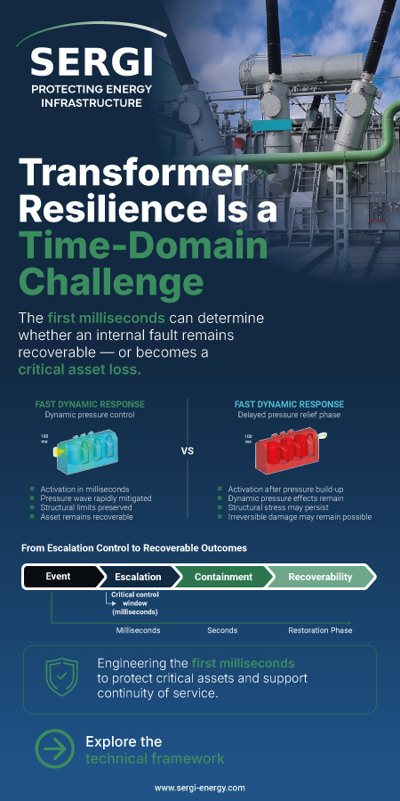
Summary
Complex insulation systems necessarily entail complex dielectric behaviour. With the mixtures of materials in multi-layer insulation it is important to remember that each layer has its own dielectric response and, when putting them together, the total response will not only reflect properties of each material, but also the way they are combined. The differences of the permittivity and volume resistivity of the materials of the different layers have the effect that the combination of materials (three layers and two layers) will respond differently to varying frequencies as the mechanisms involved to determine the stress distribution in a complex insulation system is totally different to a single layer insulation system. From previous research on multi-layer insulation cables it was shown that when these joined insulation materials are forming interfaces, charge accumulation occurs at the interfaces due to the differences between their electrical properties. With an applied voltage at higher frequencies the permittivities of the materials determine the voltage and stress distribution. When low frequencies are applied the volume resistivity of the materials determines the voltage and stress distribution in the multi-layer insulation system. When a given electric field is applied to a dielectric material, different mechanisms of polarization and conduction are activated. There will be dielectric relaxation within the insulation molecules due to the movement under the changing field, and the rate of change is determined by the relaxation time. This phenomena influence permittivity and dielectric losses. In a heterogeneous dielectric polarization is generated as a result of two or more materials having different dielectric constants, charge is accumulated at the interfaces. This is referred to as interfacial polarization, and conductivity differences will also exist. Space charge can build up at these interfaces leading to dielectric losses. Dielectric loss is measured by the dissipation factor (tan d). Tan d is the ratio of the resistive current to the capacitive charging current flowing in the cable. The resistive current is in phase with the applied voltage but the capacitive current leads the applied voltage by 900 . The vector sum of the two currents is the total current flowing. Finite Element analysis software, QuickfieldTM, will be used to simulate the Tan delta values in complex insulation systems comprising of different dielectric materials. This paper will investigate the resistive and capacitive charging current of the various insulation materials of the complex insulation system taking into consideration the conditions and results of the previous research conducted and discussed.
Additional informations
| Publication type | ISH Collection |
|---|---|
| Reference | ISH2017_260 |
| Publication year | |
| Publisher | ISH |
| File size | 534 KB |
| Pages number | 6 |
| Price for non member | Free |
| Price for member | Free |
Keywords
complex insulation, polarization, dissipation factor, finite element analysis